
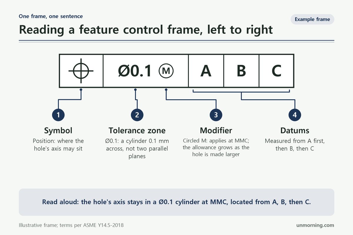
Somewhere on your part’s drawing is a small boxed row of symbols, letters and a number: a feature control frame. Read aloud, each one is a single sentence about how a feature may vary and where it is measured from. This guide is about reading that sentence.
A frame is a sentence, read left to right
Every feature control frame is a row of compartments, and the order never changes. The first compartment holds a symbol naming the geometric characteristic being controlled. The second holds the tolerance: the size of the zone the feature must stay inside. A diameter sign in front of the number means the zone is a cylinder rather than two parallel planes, which matters for holes and pins. Next to the number there may be a material condition modifier, an M or an L in a circle. The remaining compartments list datums, the reference features measurement starts from, in order of precedence.
Put together, a position frame for a hole that reads position, diameter 0.1 at MMC, A, B, C becomes a full sentence: the axis of this hole must sit inside a cylinder 0.1 mm across, located from datum A first, then B, then C, and the allowance grows as the hole is made larger than its smallest size. Translating frames into sentences like this is a reliable way to stop seeing them as hieroglyphics.
Five families, twelve characteristics
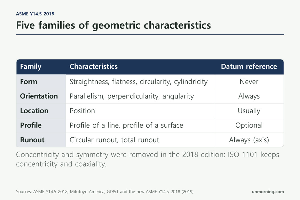
The current American standard is ASME Y14.5-2018, reaffirmed in 2024, which replaced the 2009 edition. ASME describes it as the document that establishes the symbols, rules, definitions and recommended practices for dimensioning and tolerancing on both drawings and digital models. Its characteristics fall into five families, and knowing the family tells you most of what a frame is about before you look at the number.
Form (straightness, flatness, circularity, cylindricity) controls a feature’s own shape and never references a datum. Orientation (parallelism, perpendicularity, angularity) controls tilt relative to a datum, so it always has one. Location is position, the workhorse for holes and pins, usually tied to a datum framework. Profile (of a line or of a surface) can control the shape of a curved surface alone or, with datums, its size, orientation and location together. Runout (circular and total) checks a feature while the part rotates around a datum axis.
Profile deserves a designer’s attention. ASME notes that the 2018 revision emphasises profile for location tolerances applied to surfaces. For anyone who draws freeform housings, that is good news: a single profile callout can hold a sculpted face to its CAD surface without a forest of plus-minus dimensions.
What the 2018 edition removed
Older drawings and many training charts still show two more symbols: concentricity and symmetry. A 2019 presentation from Mitutoyo America’s metrology education group lists among the significant changes in Y14.5-2018 that both tolerances have been removed entirely, the term and the symbol along with the concept, with the stated aim to “eliminate the confusion that surrounds these symbols and their misapplication.” The same material points out that many organisations had stopped using them long before, and that position and runout are the better tools for locating coaxial features.
The catch is that ISO 1101, the international counterpart, defines (as of the 2019 comparison) concentricity and coaxiality, and the meanings are not identical: under the 2009 ASME definition concentricity controlled the median points of opposed surface elements, while ISO concentricity controls a centre point and ISO coaxiality controls a derived median line. If you see the bullseye symbol on a supplier drawing, the first question is which standard the drawing invokes.
Datums decide where measurement starts
The datum compartments are where design intent hides. The order of letters is not alphabetical decoration; it is the order in which the part is constrained for measurement. The primary datum, often a large flat face, takes away the most freedom of movement, the secondary takes away fewer, and the tertiary locks what is left. ASME lists datum references and degrees of freedom among the important changes in the 2018 edition, a sign of how central this idea has become.
For a designer, the practical reading is simple. The face named as datum A is the one the engineer believes the part sits on or locates from in the assembly. If that is not the face you imagined the product resting on, you have found a disagreement worth a five-minute conversation. Why functional surfaces make good datums is introduced in the unmorning guide to reading tolerance and dimensioning on technical drawings.
Material condition and the bonus you can bank
The circled M stands for maximum material condition (MMC): the state in which the feature contains the most material, which for a hole is its smallest allowed diameter and for a pin its largest. When a position tolerance is applied at MMC, the stated value holds only at that size. As the hole is produced larger, it departs from MMC, and the position allowance grows by the same amount. With no modifier, the tolerance applies regardless of feature size and never grows.
| Hole as produced (size limits 10.0 to 10.2 mm) | Departure from MMC | Position tolerance available |
|---|---|---|
| 10.0 mm (MMC) | 0.0 mm | Ø0.1 mm |
| 10.1 mm | 0.1 mm | Ø0.2 mm |
| 10.2 mm (LMC) | 0.2 mm | Ø0.3 mm |
The worked numbers above are an illustration, not values from any standard. They show why MMC is common on clearance holes for screws: a bigger hole gives the screw more room, so the hole can afford to wander a little further without stopping assembly. Where location must stay fixed no matter the size, such as a bore that positions a bearing, the frame is more likely to carry no modifier. Reading which one the engineer chose tells you whether the feature’s job is to let parts pass through or to hold them precisely.
A quick test for any frame on your own part: say it as a sentence, then ask what would fail if the zone doubled. If nobody can name a rattle, a gap or a misaligned seam, the tolerance may be tighter than the product needs.
ASME or ISO: check the title block first
Two systems share most of their symbols, which makes the differences easy to miss. The Mitutoyo presentation cites two views from the field: Lowell Foster’s estimate in 1994 of 90 to 95 percent agreement between ASME and ISO, and Alex Krulikowski’s 2010 figure that about 65 percent of possible tolerances are specified or interpreted differently. The gap between those numbers is itself the lesson.
One concrete difference concerns plain size tolerances. In ASME Y14.5, a size tolerance controls both the actual mating size and the local size. In ISO, a size tolerance controls only a two-point size unless the drawing says otherwise, and the envelope symbol, a circled E, is used to bring mating size under control. A drawing that does not state which standard applies leaves this to the reader’s assumption, so the standard reference in the title block belongs on the list in any production handoff checklist.
Practise on drawings nobody will ship
The awkward part of learning GD&T is finding real, fully toleranced examples. The US National Institute of Standards and Technology publishes free CAD models and STEP files from its PMI validation and conformance testing project. The set includes fully toleranced test cases, simplified versions created in 2023 and a hole test case added in 2024, and NIST allows their use without restriction and asks for acknowledgment. The original cases come from a project that ended in 2015, so do not be surprised by a symbol the 2018 edition has since dropped. NIST is also clear that these are valid presentations of GD&T rather than best-practice examples, which suits a reading exercise.
A useful drill: open one model, pick five frames, write each as a sentence, and sort them into the five families. Then look at how the parts meet. If you already document assemblies with exploded views, you will notice that the tightest frames cluster where parts touch. That pattern is the engineer’s map of what the product cannot afford to get wrong, drawn in a language you can now read.
Sources
- ASME, Y14.5 Dimensioning and Tolerancing (2018 edition, reaffirmed 2024)
- Jim Salsbury, Mitutoyo America, GD&T and the new ASME Y14.5-2018 (2019, PDF)
- NIST, Download Free CAD Models, STEP Files, and Test Results (MBE PMI Validation and Conformance Testing)
한국에 온 외국인 친구가 있나요? 메뉴 번역·택시 요금·약국 카드가 한 앱에 있는 K-OREA를 알려 주세요.
Visiting Korea? K-OREA puts menu scanning, taxi fare guidance and a pharmacy card in one app. Get it on the App Store.